Enabling an Off-Board Sensor in an Existing Application
This tutorial shows you how to enable an existing application to run on a device with an off-board sensor device connected to it. It allows you to quickly bring up and run a Mynewt application on a device to view sensor data from a sensor device.
We use the sensors_test application running on an nRF52-DK board to
communicate, via the I2C interface, with the Adafruit
BNO055
sensor. The sensors_test application is a sample application that
demonstrates all the features of the Mynewt sensor framework. The
application includes the sensor framework sensor shell command that
allows you to view the sensors and sensor data managed by the sensor
framework, and the bno055 shell command that allows you to control
and query the BNO055 device and to view the sensor data.
This tutorial shows you how to:
Create and build the application and bootloader targets.
Connect a BNO055 sensor device to an nRF52-DK board.
Run
sensorandbno055shell commands to view the sensor data and control the bno055 sensor device.
Prerequisites
Meet the prerequisites listed in Sensor Tutorials
Have a Nordic nRF52-DK board.
Have an Adafruit BNO055 sensor.
Have a serial port setup
Install the Segger JLINK software and documentation pack.
Description of the Packages Needed for the Sample Application
The sensors_test application includes all the packages, and sets the
syscfg settings to values, that are required to enable the full set of
sensor framework features. This tutorial uses a subset of the
sensors_test application functionality because the objective of the
tutorial is to show you how to quickly bring up the sensors_test
application and use the sensor and bno055 shell commands to view
the sensor data from the BNO055 sensor. The instructions in this
tutorial show the syscfg settings that must be enabled in the
sensors_test application to demonstrate the examples shown. The
instructions do not explicity exclude the packages or change the syscfg
setting values to disable the functionality that is not used in the
sensors_test application.
For your reference, we describe the packages and the setting values that enable the application functionality that this tutorial demonstrates:
hw/sensor: The sensor framework package. This package defines the
SENSOR_CLIsetting that specifies whether thesensorshell command is enabled. This setting is enabled by default.hw/sensor/creator: The sensor creator package. This package supports off-board sensor devices. This package creates the os devices in the kernel for the sensors and configures the sensor devices with default values. It defines a syscfg setting for each sensor device and uses the naming convention
<SENSORNAME>_OFB. For example, the syscfg setting for the BNO055 sensor isBNO055_OFB. The<SENSORNAME>_OFBsetting specifies whether the sensor named SENSORNAME is enabled. The setting is disabled by default. This package includes the sensor device driver packagehw/drivers/sensors/<sensorname>and creates and configures a sensor named SENSORNAME when theSENSORNAME_OFBsetting is enabled by the application.hw/drivers/sensors/bno055: The driver package for the BNO055 sensor. The creator package adds this package as a package dependency when the
BNO055_OFBsetting is enabled. The driver package defines theBNO055_CLIsetting that specfies whether thebno055shell command is enabled. This setting is disabled by default and is enabled by the application. The package also exports thebno055_shell_init()function that an application calls to initialize the driver shell support.Note: All sensor driver packages that support a sensor shell command define a syscfg setting to specify whether the shell command is enabled. They also export a shell initialization function that an application must call. The naming convention is
<SENSORNAME>_CLIfor the syscfg setting and<sensorname>_shell_init()for the initialization function.sys/shell and sys/console/full: The shell and console packages for shell support over the console. The
SHELL_TASKsetting needs to be set to enable the shell support in the package. The sensors_test application enables this setting by default.
Step 1: Creating the Application Target
In this step, you create a target for the sensors_test application that enables the BNO055 off-board sensor.
To add the BNO055 sensor support, you create the application target with the following syscfg settings enabled:
I2C_0: Enables the I2C interface 0 in the nRF52 BSP HAL setting.BNO055_OFB: Enables support for the BNO055 sensor in the sensor creator package (hw/sensor/creator).When this setting is enabled, the creator package performs the following:Includes the BNO055 driver package (
hw/drivers/sensors/bno055) as a package dependency.Creates an os device for the sensor in the Mynewt kernel.
Configures the sensor device with default values.
BNO055_CLI: Enables thebno055shell command in the bno055 device driver package. The sensors_test application also uses this setting to conditionally include the call to thebno055_shell_init()function to initialize the shell support in the driver.
Note: This tutorial uses the sensor and the bno055 shell
commands. The SENSOR_CLI setting, that specifies whether the
sensor shell command is enabled, is enabled by default.
Run the
newt target createcommand, from your project base directory, to create the target. We name the targetnrf52_bno055_test:
$ newt target create nrf52_bno055_test
Target targets/nrf52_bno055_test successfully created
$
Run the
newt target setcommand to set the app, bsp, and build_profile variables for the target:
$ newt target set nrf52_bno055_test app=@apache-mynewt-core/apps/sensors_test bsp=@apache-mynewt-core/hw/bsp/nrf52dk build_profile=debug
Target targets/nrf52_bno055_test successfully set target.app to @apache-mynewt-core/apps/sensors_test
Target targets/nrf52_bno055_test successfully set target.bsp to @apache-mynewt-core/hw/bsp/nrf52dk
Target targets/nrf52_bno055_test successfully set target.build_profile to debug

$
Run the
newt target setcommand to enable theI2C_0,BNO055_OFB, andBBNO055_CLIsyscfg settings:
$ newt target set nrf52_bno055_test syscfg=BNO055_OFB=1:I2C_0=1:BNO055_CLI=1
Target targets/nrf52_bno055_test successfully set target.syscfg to BNO055_OFB=1:I2C_0=1:BNO055_CLI=1
$
Step 2: Creating the Bootloader Target
Run the following newt target commands, from your project directory, to create a
bootloader target. We name the target nrf52_boot:
$ newt target create nrf52_boot
Target targets/nrf52_boot successfully created
$ newt target set nrf52_boot app=@mcuboot/boot/mynewt bsp=@apache-mynewt-core/hw/bsp/nrf52dk  build_profile=optimized
Target targets/nrf52_boot successfully set target.app to @mcuboot/boot/mynewt
Target targets/nrf52_boot successfully set target.bsp to @apache-mynewt-core/hw/bsp/nrf52dk
Target targets/nrf52_boot successfully set target.build_profile to optimized
$
Step 3: Building the Bootloader and Application Image
Run the
newt build nrf52_bootcommand to build the bootloader:
$ newt build nrf52_boot
Building target targets/nrf52_boot
Compiling repos/mcuboot/boot/bootutil/src/image_ec.c
Compiling repos/mcuboot/boot/bootutil/src/image_rsa.c
Compiling repos/mcuboot/boot/bootutil/src/image_ec256.c
Compiling repos/mcuboot/boot/bootutil/src/loader.c
Compiling repos/mcuboot/boot/bootutil/src/bootutil_misc.c
Compiling repos/mcuboot/boot/mynewt/src/main.c

   ...

Archiving sys_mfg.a
Archiving sys_sysinit.a
Archiving util_mem.a
Linking ~/dev/myproj/bin/targets/nrf52_boot/app/boot/mynewt/mynewt.elf
Target successfully built: targets/nrf52_boot
Run the
newt build nrf52_bno055_testcommand to build the sensors_test application:
$ newt build nrf52_bno055_test
Building target targets/nrf52_bno055_test
Compiling repos/mcuboot/boot/bootutil/src/image_ec.c
Compiling repos/mcuboot/boot/bootutil/src/image_rsa.c
Compiling repos/mcuboot/boot/bootutil/src/image_ec256.c
Compiling repos/mcuboot/boot/bootutil/src/image_validate.c
Compiling repos/mcuboot/boot/bootutil/src/bootutil_misc.c
Compiling repos/apache-mynewt-core/apps/sensors_test/src/misc.c
Compiling repos/apache-mynewt-core/apps/sensors_test/src/gatt_svr.c
Compiling repos/apache-mynewt-core/apps/sensors_test/src/main.c

   ...

Compiling repos/apache-mynewt-core/hw/drivers/sensors/bno055/src/bno055.c
Compiling repos/apache-mynewt-core/hw/drivers/sensors/bno055/src/bno055_shell.c

   ...

Compiling repos/apache-mynewt-core/hw/sensor/src/sensor.c
Compiling repos/apache-mynewt-core/hw/sensor/src/sensor_oic.c
Compiling repos/apache-mynewt-core/hw/sensor/src/sensor_shell.c
Compiling repos/apache-mynewt-core/hw/sensor/creator/src/sensor_creator.c

    ...

Archiving util_mem.a
Archiving util_parse.a
Linking ~/dev/myproj/bin/targets/nrf52_bno055_test/app/apps/sensors_test/sensors_test.elf
Target successfully built: targets/nrf52_bno055_test
Step 4: Creating an Application Image
Run the newt create-image command to create an image file. You may
assign an arbitrary version (e.g. 1.0.0) to the image.
$ newt create-image nrf52_bno055_test 1.0.0
App image succesfully generated: ~/dev/myproj/bin/targets/nrf52_bno055_test/app/apps/sensors_test/sensors_test.img
Step 5: Connecting the BNO055 Sensor to the nRF52-DK Board
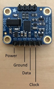
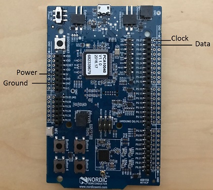
Connect the pins from the BNO055 sensor to the nRF52-DK board as specified in the following table:
Lines |
BNO055 Pin |
nRF52-DK Pin |
|---|---|---|
Power |
Vin |
5V |
Clock |
SCL |
P0.27 |
Data |
SDA |
P0.26 |
Ground |
GND |
GND |
Step 6: Connecting the nRF52-DK Board to your Computer
Set up two connections between your computer and the nRF52-DK board:
A serial connection to communicate with the sensors_test application and view the sensor data and hardware information via the Mynewt shell.
You can reference the Serial Port Setup tutorial for more information on setting up a serial communication.
A connection from your computer to the micro-USB port on the nRF52-DK board to power the board and to load the bootloader and application image.
Turn the power on the board to ON. You should see the green LED light up on the board.
Step 7: Loading the Bootloader and the Application Image
Run the
newt load nrf52_bootcommand to load the bootloader onto the board:
$ newt load nrf52_boot
Loading bootloader
$
Run the
newt load nrf52_bno055_testcommand to load the application image on to the board:
$ newt load nrf52_bno055_test
Loading app image into slot 1
$
Power the nRF52-DK board OFF and ON.
Step 8: Using a Terminal Emulator to Connect to the Application Console
Start up a terminal emulator to connect the sensors_test application console. You can use one of the terminal emulators listed below or one of your choice:
On Mac OS and Linux platforms, you can run
minicom -D /dev/tty.usbserial-<port> -b 115200to connect to the console of your app. Note that on Linux, the format of the port name is/dev/ttyUSB<N>, where N is a number.On Windows, you can use a terminal application such as PuTTY to connect to the device.
If you located your port from a MinGW terminal, the port name format is
/dev/ttyS<N>, whereNis a number. You must map the port name to a Windows COM port:/dev/ttyS<N>maps toCOM<N+1>. For example,/dev/ttyS2maps toCOM3.You can also use the Windows Device Manager to locate the COM port.
We use minicom for this tutorial. After minicom connects, enter
<return> to ensure the shell is running. You should see the compat>
prompt:
Welcome to minicom 2.7.1

OPTIONS:
Compiled on May 17 2017, 15:29:14.
Port /dev/tty.usbserial, 13:55:21

Press Meta-Z for help on special keys


010674 compat>
Step 9: Viewing the Registered Sensors and Sensor Data
The sensor framework package implements the sensor shell command. This command
allows you to:
List all the registered sensor devices.
View the sensor types that a registered sensor device supports.
Read sensor data samples.
To view the command syntax, enter sensor
002340 Possible commands for sensor are:
002341   list
002341       list of sensors registered
002342   read <sensor_name> <type> [-n nsamples] [-i poll_itvl(ms)] [-d poll_du]
002344       read <no_of_samples> from sensor<sensor_name> of type:<type> at pr
002347       at <poll_interval> rate for <poll_duration>
002348   type <sensor_name>
002349       types supported by registered sensor
002350 compat>
Listing the Registered Sensors
You use the sensor list command to list all the registered sensor devices:
031798 compat> sensor list
129441 sensor dev = bno055_0, configured type = 0x1 0x2 0x4 0x200 0x1000 0x2000
129444 compat>
The output shows one sensor, bno055_0, registered, and the configured types for the sensor. A configure type is a subset of the types that a sensor supports.
Listing the Types that a Sensor Supports
You use the sensor type command to list the types that a sensor
supports:
031822 compat> sensor type bno055_0
033156 sensor dev = bno055_0,
type =
033157     accelerometer: 0x1
033157     magnetic field: 0x2
033158     gyroscope: 0x4
033159     temperature: 0x10
033160     vector: 0x200
033160     accel: 0x1000
033161     gravity: 0x2000
033162     euler: 0x4000
Viewing Sensor Data Samples
You use the sensor read command to
read data samples for a configured type. You can specify the number of
samples to read, a poll interval, and a poll duration. You can only view
sensor data for the sensor types that a sensor device is configured for.
Example 1: Read 5 samples of accelerometer data from the bno055_0 sensor:
033163 compat> sensor read bno055_0 0x1 -n 5
042974 ts: [ secs: 335 usecs: 745441 cputime: 336218225 ]
042976 x = -0.519999968 y = -7.289999968 z = 6.489999776
042978 ts: [ secs: 335 usecs: 771216 cputime: 336244000 ]
042979 x = -0.529999968 y = -7.360000128 z = 6.559999936
042981 ts: [ secs: 335 usecs: 794640 cputime: 336267424 ]
042982 x = -0.529999968 y = -7.340000160 z = 6.480000032
042983 ts: [ secs: 335 usecs: 810795 cputime: 336283579 ]
042984 x = -0.519999968 y = -7.300000192 z = 6.530000224
042986 ts: [ secs: 335 usecs: 833703 cputime: 336306487 ]
042987 x = -0.510000000 y = -7.309999936 z = 6.380000128
Each sample contains two lines of output. The first line is the time when the sample is read. The second line is the sample data. For the example output:
These two lines are for the first sample:
042974 ts: [ secs: 335 usecs: 745441 cputime: 336218225 ]
042976 x = -0.519999968 y = -7.289999968 z = 6.489999776
These two lines are for the last sample:
042986 ts: [ secs: 335 usecs: 833703 cputime: 336306487 ]
042987 x = -0.510000000 y = -7.309999936 z = 6.380000128
Example 2: Read the vector data at 20 ms poll interval. You can
enter ctrl-c, q <return>, or Q <return> to stop the polling.
002350 compat> sensor read bno055_0 0x200 -i 20
019271 ts: [ secs: 150 usecs: 560056 cputime: 151019584 ]
019272 x = 3.442626944 y = 0.026977540 z = 3.993286144 w = 0.829833984
019274 ts: [ secs: 150 usecs: 580598 cputime: 151040126 ]
019275 x = 3.442626944 y = 0.026977540 z = 3.993286144 w = 0.829833984
019277 ts: [ secs: 150 usecs: 604036 cputime: 151063564 ]
019278 x = 3.442626944 y = 0.026977540 z = 3.993286144 w = 0.829833984
019280 ts: [ secs: 150 usecs: 627474 cputime: 151087002 ]
019281 x = 3.442626944 y = 0.026977540 z = 3.993286144 w = 0.829833984
019283 ts: [ secs: 150 usecs: 650912 cputime: 151110440 ]
019284 x = 3.442626944 y = 0.026977540 z = 3.993286144 w = 0.829833984
019286 ts: [ secs: 150 usecs: 674350 cputime: 151133878 ]
019287 x = 3.442626944 y = 0.026977540 z = 3.993286144 w = 0.829833984
019289 ts: [ secs: 150 usecs: 697788 cputime: 151157316 ]
019290 x = 3.442626944 y = 0.026977540 z = 3.993286144 w = 0.829833984
019292 ts: [ secs: 150 usecs: 721225 cputime: 151180753 ]
019293 x = 3.442626944 y = 0.026977540 z = 3.993286144 w = 0.829833984
019295 ts: [ secs: 150 usecs: 744663 cputime: 151204191 ]
019296 x = 3.442626944 y = 0.026977540 z = 3.993286144 w = 0.829833984
019298 ts: [ secs: 150 usecs: 768101 cputime: 151227629 ]
019299 x = 3.442626944 y = 0.026977540 z = 3.993286144 w = 0.829833984
019301 ts: [ secs: 150 usecs: 791539 cputime: 151251067 ]
019302 x = 3.442626944 y = 0.026977540 z = 3.993286144 w = 0.829833984
Step 10: Controlling and Viewing Sensor Device Hardware and Sensor Data
The BNO055 device driver implements the bno055 shell command
that allows you to:
Read sensor data samples for all the sensor types that the device supports.
Note: The
sensorshell command discussed previously only reads sensor data for configured sensor types.Query the chip id, sensor revisions, content of registers, sensor offsets.
Reset the device.
Change the power mode.
Change the operation mode.
Enter bno055 to see the command syntax:
   711258 bno055 cmd  [flags...]
   711259 cmd:
   711259  r     [n_samples] [ 0-acc          | 1 -mag       | 2 -gyro    | 4 -tem|
                               9-quat         | 26-linearacc | 27-gravity | 28-eul]

   711264  mode  [0-config   | 1-acc          | 2 -mag       | 3 -gyro    | 4 -acc|
                  5-accgyro  | 6-maggyro      | 7 -amg       | 8 -imuplus | 9 -com|
                  9-m4g      |11-NDOF_FMC_OFF | 12-NDOF  ]
   711269  chip_id
   711270  rev
   711270  reset
   711270  pmode [0-normal   | 1-lowpower     | 2-suspend]
   711272  sensor_offsets
   711272  dumpreg [addr]

\*\* Example 3: \*\* Query the device chip id:
711273 compat> bno055 chip_id
769056 0xA0
Example 4: View the sensor revisions:
827472 compat> bno055 rev
862354 accel_rev:0xFB
mag_rev:0x32
gyro_rev:0x0F
sw_rev:0x311
bl_rev:0x15
Next Steps
Now that you have successfully enabled an application to communicate with a sensor, We recommend that you:
Experiment with other
sensorandbno055shell commands in this tutorial to view other types of sensor data.Change the default configuration values for the sensor. See the Changing the Default Configuration for a Sensor tutorial
Try a different off-board sensor. You can follow most of the procedures in this tutorial to enable other sensors in the sensors_test application. The
syscfg.ymlfile for thehw/sensor/creator/package specifies the off-board sensors that Mynewt currently supports. You will need to:Enable the
<SENSORNAME>_OFBsetting to include the sensor driver package and to create and initialize the sensor device.Enable the correct interface in the nRF52 BSP to communicate with the sensor device.
Enable the sensor device driver shell command if the driver supports the shell. You can check the
syscfg.ymlfile for the sensor device driver package in thehw/drivers/sensor/<sensorname>directory.
Try one of the other sensor tutorials listed in the Sensor Tutorials Overview